Project 01
ARC firmware for the ARSENAL
ARC (ARSENAL Runtime Code) is C++ firmware for the ARSENAL, the custom sensor board of CBU1, built around a Seeed XIAO ESP32-S3. It reads I²C sensors and sends their data to the VEX V5 Brain over RS-485, and is meant to be reused from season to season. Benjamin Elmore is the sole author of the firmware. In a bench test on November 10, 2026, the V5 display recorded 59 replies and 0 bad packets.

Overview
Operation
The sensors of the ARSENAL sit on an I²C bus, either directly or behind I²C multiplexers. Some sensors, such as the three TMP117 temperature sensors of the ARSENAL-3, are soldered onto the board; additional sensors connect through RJ9 ports. ARC runs each sensor in its own FreeRTOS task, which selects the multiplexer channel of that sensor, reads its registers and stores the latest reading. A separate RS-485 task listens for requests from the V5 Brain and answers each read request with one packet that carries the readings of the requested sensors. The Brain can also send configuration packets, which set the type and register offsets of each sensor, and a reboot command, which restores the default offsets and clears the stored readings.
Role
I am the sole author of the ARC firmware; selected definitions, such as the sensor status codes, were retained from the legacy team firmware. I co-designed the RS-485 protocol with the teammate who writes the V5 Brain software. The CBU electronics team designed the board. Development began in August 2026 in a private team repository and continues in the public ARC repository.
Verification
On November 10, 2026, the ARSENAL-3 ran ARC on the bench with its three on-board TMP117 temperature sensors while the V5 Brain polled the board over RS-485. The captured V5 display recorded 59 replies and 0 bad packets, with valid frame markers and checksums. Each packet carries a mod-256 checksum. A failed or missing read is reported as 0xFFFF for that sensor.
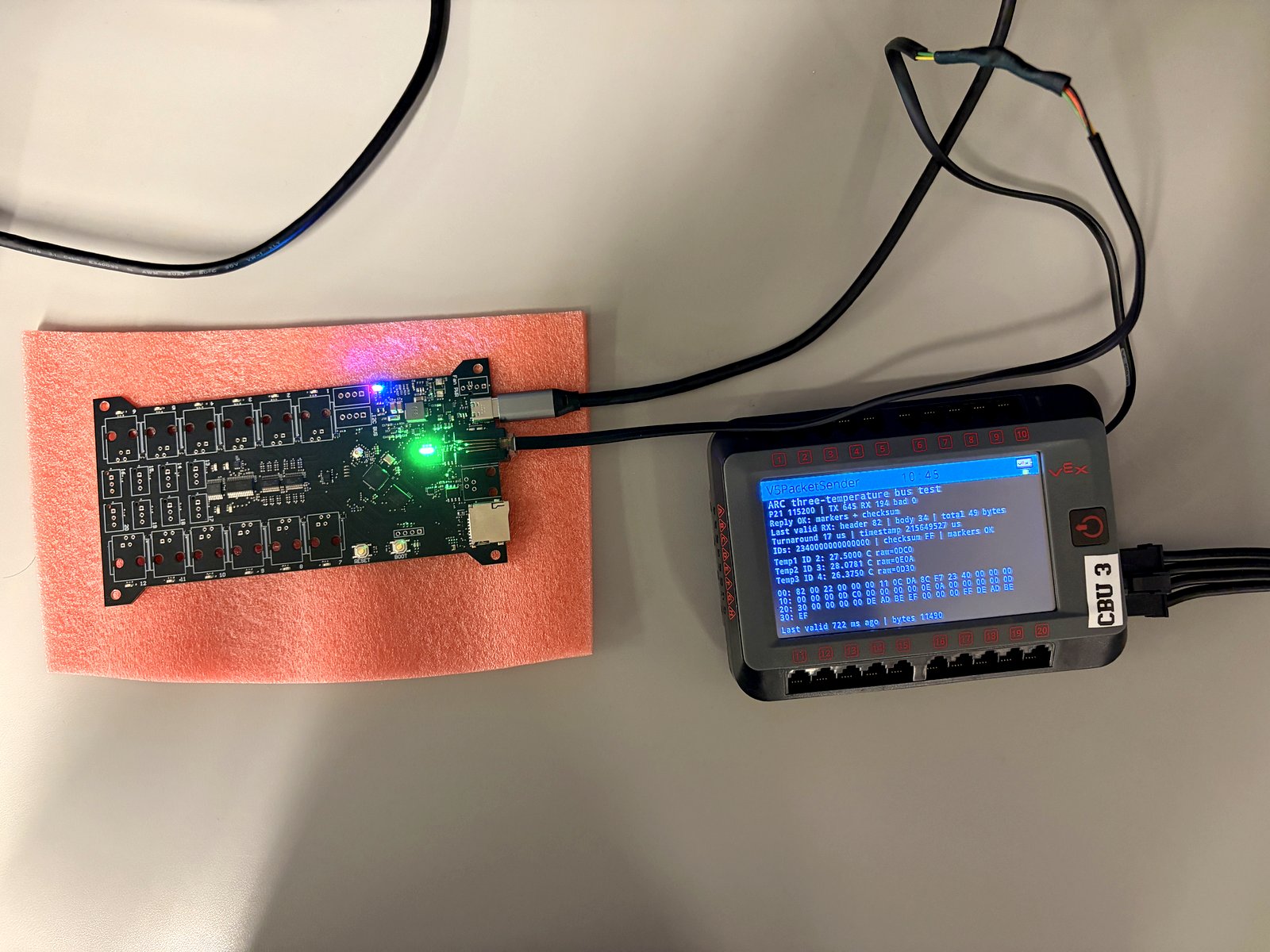
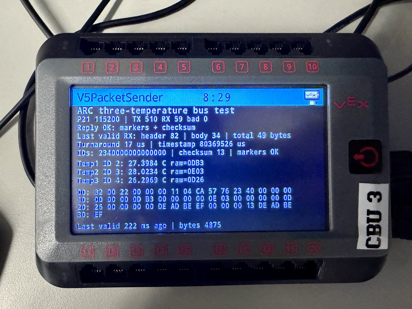
In October 2026, an earlier version of ARC ran on the ARSENAL-2.5 with the RS-485 link under isolated test, and a read request from the V5 Brain was received and parsed without error; the serial capture is in Technical detail.
Engineering decisions
- Sensor abstraction. Every sensor uses one acquisition framework, the
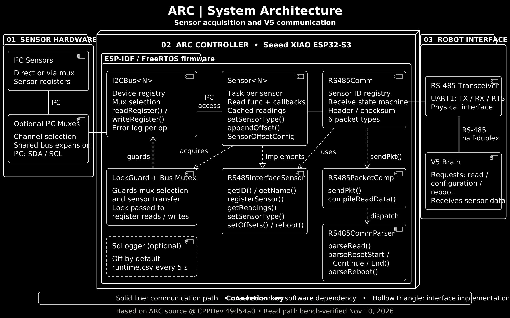
Sensor<N>template. The register reads specific to a sensor are supplied by its sensor type or by a read callback, so a new sensor needs no new class. Adding a sensor shows an example. - Shared-bus ownership. Each sensor task holds the bus mutex across multiplexer channel selection and the register transaction, so no other task can switch channels mid-read. The held lock is passed to every register read and write. Bus lock shows the guard class.
- Separate communication. A dedicated RS-485 task answers V5 requests from cached readings, so requests do not wait on sensor acquisition. Packets and configuration describes the packets.
ARC was bench-tested at CPPDev b24ce84. The class structure and code excerpts on this page come from 49d54a0; the TMP117 example comes from b24ce84.
Technical detail
Software architecture
Adding a sensor
Adding a sensor requires no new class: a Sensor<N> is configured and given one read function, either directly or through its sensor type, where N is the number of multiplexers on its bus. Each sensor task runs at a configurable priority and reports a status code on failure, and offsets, setup callbacks and loop callbacks are appendable rather than hard-coded.
- Implement a read function that receives the sensor and the held bus lock, reads the registers of the sensor through that lock and calls
setReadingswith three 16-bit values, unless the sensor type already supplies one. - Construct the
Sensor<N>with its name, bus, I²C address and ID (1 to 15). Optional arguments follow in this order: a flag to print readings (thefalsein the example below), sensor type, multiplexer channel, task priority (default 2), setup and loop callbacks, methods, variables, offsets, a read function and an offset register. - Assign a sensor type, in the constructor or with
SensorOffsetConfig::addOffsets, to attach the offset registers of that type. Atb24ce84, the temperature type also attaches its read function and offset register, so the example below passes no read function. - Call
setup()before starting RS-485. This registers the sensor on the bus, runs its initialization steps, registers it with the RS-485 link and starts its task. The RS-485 sensor registry is closed to changes once its task starts.
// src/main.cpp
namespace {
constexpr const char* TAG = "ARC";
constexpr uint8_t TMP117_ADDRESS = 0x48;
constexpr uint8_t TEMP1_ID = 2;
// ...
constexpr uint8_t TEMP1_MUX_CHANNEL = 3; // 0x70, channel 3
// ...
}
extern "C" void app_main()
{
// ...
auto& sensorBus = *I2CARSENAL::multiplexerBus;
constexpr auto temperature = SensorUtils::SensorConfig::TEMPERATURE;
static Sensor<2> temp1(
"temp1", sensorBus, TMP117_ADDRESS, TEMP1_ID, false, temperature, TEMP1_MUX_CHANNEL);
// ...
for (auto* sensor : {&temp1, &temp2, &temp3}) {
const auto status = sensor->setup();
if (status != SensorUtils::SENSOR_OK) {
ESP_LOGE(TAG, "%s setup failed: %s", sensor->getName().data(),
SensorUtils::sensor_status_str(status));
continue;
}
// ...
}
ESP_ERROR_CHECK(RS485ARSENAL::startRS485ARSENAL());
// ...
}
// lib/Sensor/ARC_Sensor.h, in the Sensor<N> constructor
// SET SENSOR TYPE
// Offsets are added and type is changed
if (sensorType != SensorUtils::SensorConfig::NONE) {
this->setSensorType(sensorType);
}
// lib/Sensor/ARC_Sensor.h, Sensor<N> members
bool setSensorType(SensorUtils::SensorConfig config) override {
// Set the type of sensor and add the relevant values needed.
this->setSensorTypeWoOffset(config);
SensorOffsetConfig::addOffsets(*this, config);
return true;
}
bool setSensorTypeWoOffset(SensorUtils::SensorConfig config) {
// Set the type of sensor on its own
this->_type = config;
if (config == SensorUtils::SensorConfig::TEMPERATURE) {
this->_readFunction = SensorOffsetConfig::readTemperature<N>;
this->_offsetMemReg = 0x07;
}
return true;
}
// lib/Sensor/SensorOffsetConfig.h
namespace SensorOffsetConfig {
template <std::size_t N>
void readTemperature(Sensor<N>& sensor, LockGuard& lock) {
constexpr uint8_t temperatureRegister = 0x00;
uint8_t temperatureBytes[2]{};
const esp_err_t readStatus = sensor.readDeviceRegister(
temperatureRegister, temperatureBytes, sizeof(temperatureBytes), lock);
if (readStatus != ESP_OK) {
return;
}
const uint16_t highByte = temperatureBytes[0];
const uint16_t lowByte = temperatureBytes[1];
const uint16_t rawTemperature = (highByte << 8) | lowByte;
sensor.setReadings({rawTemperature, 0, 0});
}
template <std::size_t N>
void addTemperatureOffsets(Sensor<N>& sensor) {
constexpr uint8_t temperatureOffsetRegister = 0x07;
constexpr uint16_t defaultTemperatureOffset = 0;
constexpr uint8_t temperaturePacketSection = 0;
constexpr uint8_t temperatureComponent = 0;
constexpr auto registerLayout = SensorUtils::OffsetLayout::REG_16_BIT_HIGH_FIRST;
sensor.appendOffset(
"offsetTemperature", defaultTemperatureOffset, temperatureOffsetRegister,
temperaturePacketSection, temperatureComponent, registerLayout);
}
// ...
// Register preset offsets once, before starting the sensor.
template <std::size_t N>
void addOffsets(Sensor<N>& sensor, SensorUtils::SensorConfig type) {
// ...
switch (type) {
case SensorUtils::SensorConfig::TEMPERATURE:
addTemperatureOffsets(sensor);
break;
// ...
}
}
}
src/main.cpp, the temperature type attaching the read function and offset register in lib/Sensor/ARC_Sensor.h, and the read function and offsets in lib/Sensor/SensorOffsetConfig.h. Omitted lines are marked // ....Bus lock
Because multiple sensor tasks share one I²C bus, every read executes under a lock. The RAII class below makes that lock difficult to misuse.
class LockGuard {
public:
explicit LockGuard(SemaphoreHandle_t& mutex) : _mutexReference(mutex) {
if (_mutexReference != nullptr &&
xSemaphoreTake(_mutexReference, portMAX_DELAY) != pdFALSE) {
_isLockedByLockGuard = true;
}
}
// Releases only if this guard took the mutex.
~LockGuard() noexcept {
if (_isLockedByLockGuard) xSemaphoreGive(_mutexReference);
}
LockGuard(const LockGuard&) = delete;
LockGuard& operator=(const LockGuard&) = delete;
bool isMutexLocked() { return _isLockedByLockGuard; }
private:
SemaphoreHandle_t& _mutexReference;
bool _isLockedByLockGuard = false;
};
lib/LockGuard.h.The lock is released automatically when the guard leaves scope, and only if this guard acquired it, so a failed acquisition can never release a lock held by another task. A register read or write is refused without a held lock, and each bus error is logged with the operation that produced it. After each read, the sensor task releases the lock, runs any loop callbacks and waits 10 ms before the next cycle.
Packets and configuration
A byte-level state machine parses incoming packets and accepts six packet types: read, a three-stage configuration sequence, reboot and failure. Read, configuration and reboot packets are dispatched to their own parsers. The RS-485 task answers each read request from the cached readings that the sensor tasks keep current.
- A read reply is a single packet containing two timestamps, up to 15 sensor IDs and six bytes of data per sensor, with DE AD BE EF frame markers around the checksum.
- Configuration runs in stages: the first packet sets the type of each sensor, the following packets carry up to three offset vectors per sensor, and the final packet writes those offsets to the registers of the sensor.
- A reboot request restores the default offsets of each sensor and clears its readings.
Specifications
| RS-485 UART | 115200 baud, 8 data bits, no parity, 1 stop bit (8N1) |
|---|---|
| Sensor IDs | 1 to 15 |
| Packet types | 6 |
| Receive buffer | 128 bytes |
| Sensor task delay | 10 ms between cycles |
| Bench read request | 37 bytes (as in the serial capture below) |
An optional SD logger records uptime and heap usage to an SD card; it is disabled by default.
Serial capture, October 2026
=== SERIAL STATUS ===
_status: ESP_OK (0)
_isFirstRead: false
_validPacket: false
_currentPacketState: WAITING_FOR_HEADER (0)
_packetLength: 22 body bytes
_timeSinceLastReceive: 0
_timeOfSending: 164438584
_packet [full buffer] (128 bytes, hex):
000: 80 00 16 00 00 00 00 09 CD 22 38 10 00 00 00 00
016: 00 00 00 00 00 00 00 00 00 DE AD BE EF 00 00 00
032: 40 DE AD BE EF 00 00 00 00 00 00 00 00 00 00 00
... (rows 048-112: all 00)
_sensorIDS (slot order): 1 0 0 0 0 0 0 0 0 0 0 0 0 0 0 0
=====================
UART received: 37
The capture shows a read request from the V5 Brain received and parsed without error: READ header, 22-byte body, sensor ID 1, valid checksum and both DE AD BE EF frame markers. _validPacket reads false because the receive loop clears the flag as soon as the reply is sent, before the status block prints. The capture predates the configuration packets.